SAFETY WARNING! Battery 12v (51 52 53 pins) power must always be active, it cannot disappear together with ignition. It is recommended that battery 12v (51 52 53 pins) be connected directly to the battery via a 15A fuse. This is required for safety reasons. The TCU keeps the parking unlocked in case of switching off the ignition while the car is moving. It is also recommended because the TCU saves adaptations when it goes to sleep. If the TCU does not go to sleep on its own before the battery power is disconnected, the adaptations will not be saved.
| TERMINAL | FUNCTION | DESCRIPTION |
|---|---|---|
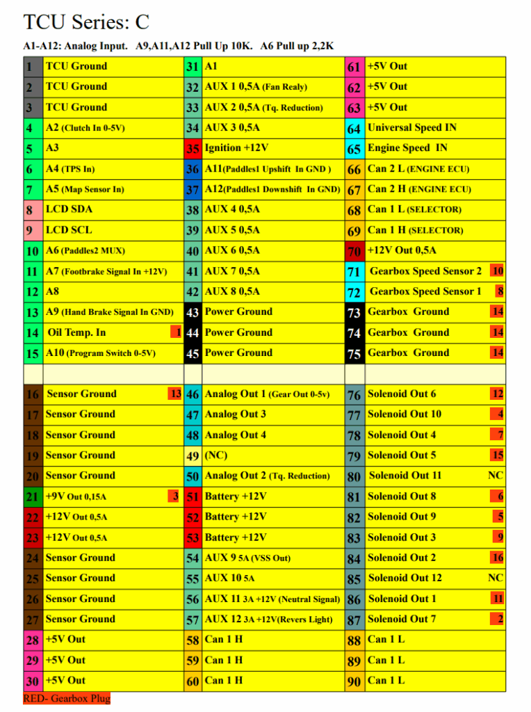
| 1-3 | TCU Ground | Device ground cable 3×0,5-1mm2 |
| 4 | A2 Clutch In 0-5V | Analog input |
| 5 | A3 | Analog input |
| 6 | A4 TPS In | Analog input |
| 7 | A5 Map Sensor In | Analog input |
| 8 | LCD SDA | LCD SDA Pin |
| 9 | LCD SCL | LCD SCL Pin |
| 10 | A6 Paddles 2 MUX | Analog input (Internal Pull Up 2,2kΩ) |
| 11 | A7 Footbrake signal in +12v | Analog input |
| 12 | A8 | Analog input |
| 13 | A9 Hand brake signal in GND | Analog input (Internal Pull Up 10kΩ) |
| 14 | Oil Temp. In | Gearbox Plug 1 |
| 15 | A10 Program switch 0-5V | Analog input |
| 16 | Sensor Ground | Ground for oil temperature sensor Gearbox Plug 13 |
| 17-20 | Sensor Ground | Ground for external sensor 17.LCD GND 18. Program Switch GND |
| 21 | +9V Out 0,15A | Power for speed sensors Gearbox Plug 3 |
| 22-23 | +12v Out 0,5A | Maximum load 0.5A |
| 24-27 | Sensor Ground | |
| 28-30 | +5V Out | |
| 31 | A1 | Analog input |
| 32 | AUX 1 0,5A Fan Relay | Oil radiator FAN |
| 33 | AUX 2 0,5A Tq. Reduction | Torque reduction signal for ECU |
| 34 | AUX 0,5A | Low side output. Maximum load 0,5A |
| 35 | Ignition +12V | Signal to switch on the TCU |
| 36 | A11 Gear shift button Up GND | Analog input (Internal Pull Up 10kΩ) |
| 37 | A12 Gear shift button Down GND | Analog input (Internal Pull Up 10kΩ) |
| 38-42 | AUX | Low side output. Maximum load 0,5A |
| 43-45 | Power ground | TCU Groung used by AUX/Solenoid cable 3×1-1,5mm2 |
| 46 | Analog out Gear Out | 0-5V |
| 47-48 | Analog out | Analog output low side (signal: clutch, rear light, neutral, etc.) Max. load 10mA |
| 50 | Analog Out 2 Tq. Reduction | Torque reduction signal for ECU |
| 51-53 | Battery +12V | Power supply all the time. 15A fused cable 3×1-1,5mm2 |
| 54 | AUX 9 5A VSS Out | Low side output. Maximum load 5A. Tacho speed output |
| 55 | AUX 10 5A | Low side output. Maximum load 5A |
| 56 | AUX 11 3A +12V Neutral signal | Hight side output. Maximum load 3A |
| 57 | AUX 12 3A +12V Reverse light | Hight side output. Maximum load 3A |
| 58 | Can 1 H | |
| 59 | Can 1 H | |
| 60 | Can 1 H | |
| 61 | +5V Out LCD | +5V power for external sensors. LCD VCC Maximum load 61,62,63 total 0,5A |
| 62-63 | +5V Out | +5V power for external sensors. Program Switch. Maximum load 61,62,63 total 0,5A |
| 64 | Universal Speed IN | |
| 65 | Engine Speed IN | |
| 66 | Can2 L (Engine ECU) | CAN L signal for CAN BUS 2 |
| 67 | Can2 H (Engine ECU) | CAN H signal for CAN BUS 2 |
| 68 | Can1 L Gear selestor | CAN L signal for CAN BUS 1 |
| 69 | Can1 H Gear selector | CAN H signal for CAN BUS 1 |
| 70 | +12V Out 0,5A | |
| 71 | Gearbox Speed Sensor 2 | Gearbox Plug 10 |
| 72 | Gearbox Speed Sensor 1 | Gearbox Plug 8 |
| 73-75 | Gearbox Ground | Solenoid Ground Gearbox Plug 1 cable 3×0,5mm2 |
| 76-79 | Solenoid Out | Gearbox Plug cable 0,5-1mm2 |
| 81-84 | Solenoid Out | Gearbox Plug cable 0,5-1mm2 |
| 86-87 | Solenoid Out | Gearbox Plug cable 0,5-1mm2 |
| 88 | Can 1 L | |
| 89 | Can 1 L | |
| 90 | Can 1 L |